In today’s era, there is a great deal added to real-time remote sensing Big Data than it seems at first, and extracting the useful information in an efficient manner leads a system toward a major computational challenges, such as to analyze, aggregate, and store, where data are remotely collected. Keeping in view the above mentioned factors, there is a need for designing a system architecture that welcomes both realtime, as well as offline data processing. In this paper, we propose real-time Big Data analytical architecture for remote sensing satellite application.
The proposed architecture comprises three main units:
1) Remote sensing Big Data acquisition unit (RSDU);
2) Data processing unit (DPU); and
3) Data analysis decision unit (DADU).
First, RSDU acquires data from the
satellite and sends this data to the Base Station, where initial processing
takes place. Second, DPU plays a vital role in architecture for efficient
processing of real-time Big Data by providing filtration, load balancing, and parallel
processing. Third, DADU is the upper layer unit of the proposed architecture,
which is responsible for compilation, storage of the results, and generation of
decision based on the results received from DPU.
1.2 INTRODUCTION:
Recently, a great deal of interest in the field of Big Data and its analysis has risen mainly driven from extensive number of research challenges strappingly related to bonafide applications, such as modeling, processing, querying, mining, and distributing large-scale repositories. The term “Big Data” classifies specific kinds of data sets comprising formless data, which dwell in data layer of technical computing applications and the Web. The data stored in the underlying layer of all these technical computing application scenarios have some precise individualities in common, such as 1) largescale data, which refers to the size and the data warehouse; 2) scalability issues, which refer to the application’s likely to be running on large scale (e.g., Big Data); 3) sustain extraction transformation loading (ETL) method from low, raw data to well thought-out data up to certain extent; and 4) development of uncomplicated interpretable analytical over Big Data warehouses with a view to deliver an intelligent and momentous knowledge for them.
Big Data are usually generated by online transaction, video/audio, email, number of clicks, logs, posts, social network data, scientific data, remote access sensory data, mobile phones, and their applications. These data are accumulated in databases that grow extraordinarily and become complicated to confine, form, store, manage, share, process, analyze, and visualize via typical database software tools. Advancement in Big Data sensing and computer technology revolutionizes the way remote data collected, processed, analyzed, and managed. Particularly, most recently designed sensors used in the earth and planetary observatory system are generating continuous stream of data. Moreover, majority of work have been done in the various fields of remote sensory satellite image data, such as change detection, gradient-based edge detection region similarity based edge detection and intensity gradient technique for efficient intraprediction.
In this paper, we referred the high speed continuous stream of data or high volume offline data to “Big Data,” which is leading us to a new world of challenges. Such consequences of transformation of remotely sensed data to the scientific understanding are a critical task. Hence the rate at which volume of the remote access data is increasing, a number of individual users as well as organizations are now demanding an efficient mechanism to collect, process, and analyze, and store these data and its resources. Big Data analysis is somehow a challenging task than locating, identifying, understanding, and citing data. Having a large-scale data, all of this has to happen in a mechanized manner since it requires diverse data structure as well as semantics to be articulated in forms of computer-readable format.
However, by analyzing simple data having one data set, a mechanism is required of how to design a database. There might be alternative ways to store all of the same information. In such conditions, the mentioned design might have an advantage over others for certain process and possible drawbacks for some other purposes. In order to address these needs, various analytical platforms have been provided by relational databases vendors. These platforms come in various shapes from software only to analytical services that run in third-party hosted environment. In remote access networks, where the data source such as sensors can produce an overwhelming amount of raw data.
We refer it to the first step, i.e., data
acquisition, in which much of the data are of no interest that can be filtered
or compressed by orders of magnitude. With a view to using such filters, they
do not discard useful information. For instance, in consideration of new
reports, is it adequate to keep that information that is mentioned with the
company name? Alternatively, is it necessary that we may need the entire
report, or simply a small piece around the mentioned name? The second challenge
is by default generation of accurate metadata that describe the composition of
data and the way it was collected and analyzed. Such kind of metadata is hard
to analyze since we may need to know the source for each data in remote access.
1.3 LITRATURE SURVEY:
BIG DATA AND CLOUD COMPUTING: CURRENT STATE AND FUTURE OPPORTUNITIES
AUTHOR: D. Agrawal, S. Das, and A. E. Abbadi
PUBLISH: Proc. Int. Conf. Extending Database Technol. (EDBT), 2011, pp. 530–533.
EXPLANATION:
Scalable database management systems (DBMS)—both for
update intensive application workloads as well as decision support systems for descriptive
and deep analytics—are a critical part of the cloud infrastructure and play an
important role in ensuring the smooth transition of applications from the
traditional enterprise infrastructures to next generation cloud
infrastructures. Though scalable data management has been a vision for more
than three decades and much research has focussed on large scale data
management in traditional enterprise setting, cloud computing brings its own
set of novel challenges that must be addressed to ensure the success of data
management solutions in the cloud environment. This tutorial presents an
organized picture of the challenges faced by application developers and DBMS
designers in developing and deploying internet scale applications. Our
background study encompasses both classes of systems: (i) for supporting update
heavy applications, and (ii) for ad-hoc analytics and decision support. We then
focus on providing an in-depth analysis of systems for supporting update
intensive web-applications and provide a survey of the state-of-theart in this
domain. We crystallize the design choices made by some successful systems large
scale database management systems, analyze the application demands and access
patterns, and enumerate the desiderata for a cloud-bound DBMS.
CHANGE DETECTION IN SYNTHETIC APERTURE RADAR IMAGE BASED ON FUZZY ACTIVE CONTOUR MODELS AND GENETIC ALGORITHMS
AUTHOR: J. Shi, J. Wu, A. Paul, L. Jiao, and M. Gong
PUBLISH: Math. Prob. Eng., vol. 2014, 15 pp., Apr. 2014.
EXPLANATION:
This paper presents an unsupervised
change detection approach for synthetic aperture radar images based on a fuzzy
active contour model and a genetic algorithm. The aim is to partition the
difference image which is generated from multitemporal satellite images into changed
and unchanged regions. Fuzzy technique is an appropriate approach to analyze
the difference image where regions are not always statistically homogeneous.
Since interval type-2 fuzzy sets are well-suited for modeling various
uncertainties in comparison to traditional fuzzy sets, they are combined with
active contour methodology for properly modeling uncertainties in the
difference image. The interval type-2 fuzzy active contour model is designed to
provide preliminary analysis of the difference image by generating intermediate
change detection masks. Each intermediate change detection mask has a cost
value. A genetic algorithm is employed to find the final change detection mask
with the minimum cost value by evolving the realization of intermediate change
detection masks. Experimental results on real synthetic aperture radar images
demonstrate that change detection results obtained by the improved fuzzy active
contour model exhibits less error than previous approaches.
A BIG DATA ARCHITECTURE FOR LARGE SCALE SECURITY MONITORING
AUTHOR: S. Marchal, X. Jiang, R. State, and T. Engel
PUBLISH: Proc. IEEE Int. Congr. Big Data, 2014, pp. 56–63.
EXPLANATION:
Network traffic is a rich source of information for
security monitoring. However the increasing volume of data to treat raises
issues, rendering holistic analysis of network traffic difficult. In this paper
we propose a solution to cope with the tremendous amount of data to analyse for
security monitoring perspectives. We introduce an architecture dedicated to
security monitoring of local enterprise networks. The application domain of
such a system is mainly network intrusion detection and prevention, but can be
used as well for forensic analysis. This architecture integrates two systems,
one dedicated to scalable distributed data storage and management and the other
dedicated to data exploitation. DNS data, NetFlow records, HTTP traffic and
honeypot data are mined and correlated in a distributed system that leverages
state of the art big data solution. Data correlation schemes are proposed and
their performance are evaluated against several well-known big data framework
including Hadoop and Spark.
CHAPTER 2
2.0 SYSTEM ANALYSIS
2.1 EXISTING SYSTEM:
Existing methods inapplicable on standard computers it is not desirable or possible to load the entire image into memory before doing any processing. In this situation, it is necessary to load only part of the image and process it before saving the result to the disk and proceeding to the next part. This corresponds to the concept of on-the-flow processing. Remote sensing processing can be seen as a chain of events or steps is generally independent from the following ones and generally focuses on a particular domain. For example, the image can be radio metrically corrected to compensate for the atmospheric effects, indices computed, before an object extraction based on these indexes takes place.
The typical processing chain will process the whole image for each step, returning the final result after everything is done. For some processing chains, iterations between the different steps are required to find the correct set of parameters. Due to the variability of satellite images and the variety of the tasks that need to be performed, fully automated tasks are rare. Humans are still an important part of the loop. These concepts are linked in the sense that both rely on the ability to process only one part of the data.
In the case of simple algorithms, this is
quite easy: the input is just split into different non-overlapping pieces that
are processed one by one. But most algorithms do consider the neighborhood of
each pixel. As a consequence, in most cases, the data will have to be split
into partially overlapping pieces. The objective is to obtain the same result
as the original algorithm as if the processing was done in one go. Depending on
the algorithm, this is unfortunately not always possible.
2.1.1 DISADVANTAGES:
- A reader that loads the image, or part of the image in memory from the file on disk;
- A filter which carries out a local processing that does not require access to neighboring pixels (a simple threshold for example), the processing can happen on CPU or GPU;
- A filter that requires the value of neighboring pixels to compute the value of a given pixel (a convolution filter is a typical example), the processing can happen on CPU or GPU;
- A writer to output the resulting image in memory into a file on disk, note that the file could be written in several steps. We will illustrate in this example how it is possible to compute part of the image in the whole pipeline, incurring only minimal computation overhead.
2.2 PROPOSED SYSTEM:
We present a remote sensing Big Data analytical architecture, which is used to analyze real time, as well as offline data. At first, the data are remotely preprocessed, which is then readable by the machines. Afterward, this useful information is transmitted to the Earth Base Station for further data processing. Earth Base Station performs two types of processing, such as processing of real-time and offline data. In case of the offline data, the data are transmitted to offline data-storage device. The incorporation of offline data-storage device helps in later usage of the data, whereas the real-time data is directly transmitted to the filtration and load balancer server, where filtration algorithm is employed, which extracts the useful information from the Big Data.
On the other hand, the load balancer balances the processing power by equal distribution of the real-time data to the servers. The filtration and load-balancing server not only filters and balances the load, but it is also used to enhance the system efficiency. Furthermore, the filtered data are then processed by the parallel servers and are sent to data aggregation unit (if required, they can store the processed data in the result storage device) for comparison purposes by the decision and analyzing server. The proposed architecture welcomes remote access sensory data as well as direct access network data (e.g., GPRS, 3G, xDSL, or WAN). The proposed architecture and the algorithms are implemented in applying remote sensing earth observatory data.
We proposed architecture has the
capability of dividing, load balancing, and parallel processing of only useful
data. Thus, it results in efficiently analyzing real-time remote sensing Big
Data using earth observatory system. Furthermore, the proposed architecture has
the capability of storing incoming raw data to perform offline analysis on
largely stored dumps, when required. Finally, a detailed analysis of remotely
sensed earth observatory Big Data for land and sea area are provided using
.NET. In addition, various algorithms are proposed for each level of RSDU, DPU,
and DADU to detect land as well as sea area to elaborate the working of
architecture.
2.2.1 ADVANTAGES:
Big Data process high-speed, large amount of real-time remote sensory image data using our proposed architecture. It works on both DPU and DADU by taking data from medical application.
Our architecture for offline as well online traffic, we perform a simple analysis on remote sensing earth observatory data. We assume that the data are big in nature and difficult to handle for a single server.
The data are continuously coming from a satellite with high speed. Hence, special algorithms are needed to process, analyze, and make a decision from that Big Data. Here, in this section, we analyze remote sensing data for finding land, sea, or ice area.
We have used the proposed architecture to perform
analysis and proposed an algorithm for handling, processing, analyzing, and
decision-making for remote sensing Big Data images using our proposed
architecture.
2.3 HARDWARE & SOFTWARE REQUIREMENTS:
2.3.1 HARDWARE REQUIREMENT:
v Processor – Pentium –IV
- Speed –
1.1 GHz
- RAM – 256 MB (min)
- Hard Disk – 20 GB
- Floppy Drive – 1.44 MB
- Key Board – Standard Windows Keyboard
- Mouse – Two or Three Button Mouse
- Monitor – SVGA
2.3.2 SOFTWARE REQUIREMENTS:
- Operating System : Windows XP or Win7
- Front End : Microsoft Visual Studio .NET 2008
- Script : C# Script
- Back End : MS-SQL Server 2005
- Document : MS-Office 2007
CHAPTER 3
3.0 SYSTEM DESIGN:
Data Flow Diagram / Use Case Diagram / Flow Diagram:
- The DFD is also called as bubble chart. It is a simple graphical formalism that can be used to represent a system in terms of the input data to the system, various processing carried out on these data, and the output data is generated by the system
- The data flow diagram (DFD) is one of the most important modeling tools. It is used to model the system components. These components are the system process, the data used by the process, an external entity that interacts with the system and the information flows in the system.
- DFD shows how the information moves through the system and how it is modified by a series of transformations. It is a graphical technique that depicts information flow and the transformations that are applied as data moves from input to output.
- DFD is also known as bubble chart. A DFD may be used to represent a system at any level of abstraction. DFD may be partitioned into levels that represent increasing information flow and functional detail.
NOTATION:
SOURCE OR DESTINATION OF DATA:
External sources or destinations, which may be people or organizations or other entities
DATA SOURCE:
Here the data referenced by a process is stored and retrieved.
PROCESS:
People, procedures or devices that produce data’s in the physical component is not identified.
DATA FLOW:
Data moves in a specific direction from an origin to a destination. The data flow is a “packet” of data.
There are several common modeling rules when creating DFDs:
- All processes must have at least one data flow in and one data flow out.
- All processes should modify the incoming data, producing new forms of outgoing data.
- Each data store must be involved with at least one data flow.
- Each external entity must be involved with at least one data flow.
- A data flow must be attached to at least one process.
3.1 ARCHITECTURE DIAGRAM:
3.2 DATAFLOW DIAGRAM:
UML DIAGRAMS:
3.2 USE CASE DIAGRAM:
3.3 CLASS DIAGRAM:
3.4 SEQUENCE DIAGRAM:
3.5 ACTIVITY DIAGRAM:
CHAPTER 4
4.0 IMPLEMENTATION:
Big Data covers diverse technologies same as cloud computing. The input of Big Data comes from social networks (Facebook, Twitter, LinkedIn, etc.), Web servers, satellite imagery, sensory data, banking transactions, etc. Regardless of very recent emergence of Big Data architecture in scientific applications, numerous efforts toward Big Data analytics architecture can already be found in the literature. Among numerous others, we propose remote sensing Big Data architecture to analyze the Big Data in an efficient manner as shown in Fig. 1. Fig. 1 delineates n number of satellites that obtain the earth observatory Big Data images with sensors or conventional cameras through which sceneries are recorded using radiations. Special techniques are applied to process and interpret remote sensing imagery for the purpose of producing conventional maps, thematic maps, resource surveys, etc. We have divided remote sensing Big Data architecture.
Healthcare scenarios, medical practitioners gather
massive volume of data about patients, medical history, medications, and other
details. The above-mentioned data are accumulated in drug-manufacturing
companies. The nature of these data is very complex, and sometimes the
practitioners are unable to show a relationship with other information, which
results in missing of important information. With a view in employing advance
analytic techniques for organizing and extracting useful information from Big
Data results in personalized medication, the advance Big Data analytic
techniques give insight into hereditarily causes of the disease.
4.1 ALGORITHM:
This algorithm takes satellite data or product and then filters and divides them into segments and performs load-balancing algorithm.
The processing algorithm calculates results for different parameters against each incoming block and sends them to the next level. In step 1, the calculation of mean, SD, absolute difference, and the number of values, which are greater than the maximum threshold, are performed. Furthermore, in the next step, the results are transmitted to the aggregation server.
ACA collects the results from each processing servers against each Bi and then combines, organizes, and stores these results in RDBMS database.
4.2 MODULES:
DATA ANALYSIS DECISION UNIT (DADU):
DATA PROCESSING UNIT (DPU):
REMOTE SENSING APPLICATION RSDU:
FINDINGS AND DISCUSSION:
ALGORITHM
DESIGN AND TESTING:
4.3 MODULE DESCRIPTION:
DATA PROCESSING UNIT (DPU):
In data processing unit (DPU), the filtration and load balancer server have two basic responsibilities, such as filtration of data and load balancing of processing power. Filtration identifies the useful data for analysis since it only allows useful information, whereas the rest of the data are blocked and are discarded. Hence, it results in enhancing the performance of the whole proposed system. Apparently, the load-balancing part of the server provides the facility of dividing the whole filtered data into parts and assign them to various processing servers. The filtration and load-balancing algorithm varies from analysis to analysis; e.g., if there is only a need for analysis of sea wave and temperature data, the measurement of these described data is filtered out, and is segmented into parts.
Each processing server has its algorithm
implementation for processing incoming segment of data from FLBS. Each
processing server makes statistical calculations, any measurements, and
performs other mathematical or logical tasks to generate intermediate results
against each segment of data. Since these servers perform tasks independently
and in parallel, the performance proposed system is dramatically enhanced, and
the results against each segment are generated in real time. The results
generated by each server are then sent to the aggregation server for
compilation, organization, and storing for further processing.
DATA ANALYSIS DECISION UNIT (DADU):
DADU contains three major portions, such as aggregation and compilation server, results storage server(s), and decision making server. When the results are ready for compilation, the processing servers in DPU send the partial results to the aggregation and compilation server, since the aggregated results are not in organized and compiled form. Therefore, there is a need to aggregate the related results and organized them into a proper form for further processing and to store them. In the proposed architecture, aggregation and compilation server is supported by various algorithms that compile, organize, store, and transmit the results. Again, the algorithm varies from requirement to requirement and depends on the analysis needs. Aggregation server stores the compiled and organized results into the result’s storage with the intention that any server can use it as it can process at any time.
The aggregation server also sends the
same copy of that result to the decision-making server to process that result
for making decision. The decision-making server is supported by the decision
algorithms, which inquire different things from the result, and then make
various decisions (e.g., in our analysis, we analyze land, sea, and ice,
whereas other finding such as fire, storms, Tsunami, earthquake can also be
found). The decision algorithm must be strong and correct enough that
efficiently produce results to discover hidden things and make decisions. The
decision part of the architecture is significant since any small error in
decision-making can degrade the efficiency of the whole analysis. DADU finally
displays or broadcasts the decisions, so that any application can utilize those
decisions at real time to make their development. The applications can be any
business software, general purpose community software, or other social networks
that need those findings (i.e., decision-making).
REMOTE SENSING APPLICATION RSDU:
Remote sensing promotes the expansion of earth observatory system as cost-effective parallel data acquisition system to satisfy specific computational requirements. The Earth and Space Science Society originally approved this solution as the standard for parallel processing in this particular qualifications for improved Big Data acquisition, soon it was recognized that traditional data processing technologies could not provide sufficient power for processing such kind of data. Therefore, the need for parallel processing of the massive volume of data was required, which could efficiently analyze the Big Data. For that reason, the proposed RSDU is introduced in the remote sensing Big Data architecture that gathers the data from various satellites around the globe as possible that the received raw data are distorted by scattering and absorption by various atmospheric gasses and dust particles. We assume that the satellite can correct the erroneous data.
However, to make the raw data into image
format, the remote sensing satellite uses effective data analysis, remote
sensing satellite preprocesses data under many situations to integrate the data
from different sources, which not only decreases storage cost, but also
improves analysis accuracy. The data must be corrected in different methods to
remove distortions caused due to the motion of the platform relative to the
earth, platform attitude, earth curvature, nonuniformity of illumination,
variations in sensor characteristics, etc. The data is then transmitted to
Earth Base Station for further processing using direct communication link. We
divided the data processing procedure into two steps, such as real-time Big
Data processing and offline Big Data processing. In the case of offline data
processing, the Earth Base Station transmits the data to the data center for
storage. This data is then used for future analyses. However, in real-time data
processing, the data are directly transmitted to the filtration and load
balancer server (FLBS), since storing of incoming real-time data degrades the
performance of real-time processing.
FINDINGS AND DISCUSSION:
Preprocessed and formatted data from satellite contains all or some of the following parts depending on the product.
1) Main product header (MPH): It includes the products basis information, i.e., id, measurement and sensing time, orbit, information, etc.
2) Special products head (SPH): It contains information specific to each product or product group, i.e., number of data sets descriptors (DSD), directory of remaining data sets in the file, etc.
3) Annotation data sets (ADS): It contains information of quality, time tagged processing parameters, geo location tie points, solar, angles, etc.
4) Global annotation data sets (GADs): It contains calling factors, offsets, calibration information, etc.
5) Measurement data set (MDS): It contains measurements or graphical parameters calculated from the measurement including quality flag and the time tag measurement as well. The image data are also stored in this part and are the main element of our analysis.
The MPH and SPH data are in ASCII
format, whereas all the other data sets are in binary format. MDS, ADS, and
GADs consist of the sequence of records and one or more fields of the data for
each record. In our case, the MDS contains number of records, and each record
contains a number of fields. Each record of the MDS corresponds to one row of
the satellite image, which is our main focus during analysis.
ALGORITHM DESIGN AND TESTING:
Our algorithms are proposed to process
high-speed, large amount of real-time remote sensory image data using our
proposed architecture. It works on both DPU and DADU by taking data from
satellite as input to identify land and sea area from the data set. The set of
algorithms contains four simple algorithms, i.e., algorithm I, algorithm II,
algorithm III, and algorithm IV that work on filtrations and load balancer,
processing servers, aggregation server, and on decision-making server,
respectively. Algorithm I, i.e., filtration and load balancer algorithm (FLBA)
works on filtration and load balancer to filter only the require data by
discarding all other information. It also provides load balancing by dividing
the data into fixed size blocks and sending them to the processing server,
i.e., one or more distinct blocks to each server. This filtration, dividing,
and load-balancing task speeds up our performance by neglecting unnecessary
data and by providing parallel processing. Algorithm II, i.e., processing and
calculation algorithm (PCA) processes filtered data and is implemented on each
processing server. It provides various parameter calculations that are used in
the decision-making process. The parameters calculations results are then sent
to aggregation server for further processing. Algorithm III, i.e., aggregation
and compilations algorithm (ACA) stores, compiles, and organizes the results,
which can be used by decision-making server for land and sea area detection.
Algorithm IV, i.e., decision-making algorithm (DMA) identifies land area and
sea area by comparing the parameters results, i.e., from aggregation servers,
with threshold values.
CHAPTER 5
5.0 SYSTEM STUDY:
5.1 FEASIBILITY STUDY:
The feasibility of the project is analyzed in this phase and business proposal is put forth with a very general plan for the project and some cost estimates. During system analysis the feasibility study of the proposed system is to be carried out. This is to ensure that the proposed system is not a burden to the company. For feasibility analysis, some understanding of the major requirements for the system is essential.
Three key considerations involved in the feasibility analysis are
- ECONOMICAL FEASIBILITY
- TECHNICAL FEASIBILITY
- SOCIAL FEASIBILITY
5.1.1 ECONOMICAL FEASIBILITY:
This study is carried out to check the economic impact that the system will have on the organization. The amount of fund that the company can pour into the research and development of the system is limited. The expenditures must be justified. Thus the developed system as well within the budget and this was achieved because most of the technologies used are freely available. Only the customized products had to be purchased.
5.1.2 TECHNICAL FEASIBILITY:
This study is carried out to check the technical feasibility, that is, the technical requirements of the system. Any system developed must not have a high demand on the available technical resources. This will lead to high demands on the available technical resources. This will lead to high demands being placed on the client. The developed system must have a modest requirement, as only minimal or null changes are required for implementing this system.
5.1.3 SOCIAL FEASIBILITY:
The aspect of study is to check the level of
acceptance of the system by the user. This includes the process of training the
user to use the system efficiently. The user must not feel threatened by the
system, instead must accept it as a necessity. The level of acceptance by the
users solely depends on the methods that are employed to educate the user about
the system and to make him familiar with it. His level of confidence must be
raised so that he is also able to make some constructive criticism, which is
welcomed, as he is the final user of the system.
5.2 SYSTEM TESTING:
Testing is a process of checking whether the developed system is working according to the original objectives and requirements. It is a set of activities that can be planned in advance and conducted systematically. Testing is vital to the success of the system. System testing makes a logical assumption that if all the parts of the system are correct, the global will be successfully achieved. In adequate testing if not testing leads to errors that may not appear even many months. This creates two problems, the time lag between the cause and the appearance of the problem and the effect of the system errors on the files and records within the system. A small system error can conceivably explode into a much larger Problem. Effective testing early in the purpose translates directly into long term cost savings from a reduced number of errors. Another reason for system testing is its utility, as a user-oriented vehicle before implementation. The best programs are worthless if it produces the correct outputs.
5.2.1 UNIT TESTING:
A program represents the
logical elements of a system. For a program to run satisfactorily, it must
compile and test data correctly and tie in properly with other programs.
Achieving an error free program is the responsibility of the programmer.
Program testing checks
for two types
of errors: syntax
and logical. Syntax error is a
program statement that violates one or more rules of the language in which it
is written. An improperly defined field dimension or omitted keywords are
common syntax errors. These errors are shown through error message generated by
the computer. For Logic errors the programmer must examine the output
carefully.
UNIT TESTING:
| Description | Expected result |
| Test for application window properties. | All the properties of the windows are to be properly aligned and displayed. |
| Test for mouse operations. | All the mouse operations like click, drag, etc. must perform the necessary operations without any exceptions. |
5.1.3 FUNCTIONAL TESTING:
Functional testing of an
application is used to prove the application delivers correct results, using
enough inputs to give an adequate level of confidence that will work correctly
for all sets of inputs. The functional testing will need to prove that the application
works for each client type and that personalization function work correctly.When a program is tested, the actual output is compared with the expected
output. When there is a discrepancy the sequence of instructions must be traced
to determine the problem. The process is
facilitated by breaking the program into self-contained portions, each of which
can be checked at certain key points. The idea is to compare program values
against desk-calculated values to isolate the problems.
FUNCTIONAL TESTING:
| Description | Expected result |
| Test for all modules. | All peers should communicate in the group. |
| Test for various peer in a distributed network framework as it display all users available in the group. | The result after execution should give the accurate result. |
5.1. 4 NON-FUNCTIONAL TESTING:
The Non Functional software testing encompasses a rich spectrum of testing strategies, describing the expected results for every test case. It uses symbolic analysis techniques. This testing used to check that an application will work in the operational environment. Non-functional testing includes:
- Load testing
- Performance testing
- Usability testing
- Reliability testing
- Security testing
5.1.5 LOAD TESTING:
An important tool for implementing system tests is a Load generator. A Load generator is essential for testing quality requirements such as performance and stress. A load can be a real load, that is, the system can be put under test to real usage by having actual telephone users connected to it. They will generate test input data for system test.
Load Testing
| Description | Expected result |
| It is necessary to ascertain that the application behaves correctly under loads when ‘Server busy’ response is received. | Should designate another active node as a Server. |
5.1.5 PERFORMANCE TESTING:
Performance tests are
utilized in order to determine the widely defined performance of the software
system such as execution time associated with various parts of the code,
response time and device utilization. The intent of this testing is to identify
weak points of the software system and quantify its shortcomings.
PERFORMANCE TESTING:
| Description | Expected result |
| This is required to assure that an application perforce adequately, having the capability to handle many peers, delivering its results in expected time and using an acceptable level of resource and it is an aspect of operational management. | Should handle large input values, and produce accurate result in a expected time. |
5.1.6 RELIABILITY TESTING:
The software reliability
is the ability of a system or component to perform its required functions under
stated conditions for a specified period of time and it is being ensured in
this testing. Reliability can be expressed as the ability of the software to
reveal defects under testing conditions, according to the specified
requirements. It the portability that a software system will operate without
failure under given conditions for a given time interval and it focuses on the
behavior of the software element. It forms a part of the software quality
control team.
RELIABILITY TESTING:
| Description | Expected result |
| This is to check that the server is rugged and reliable and can handle the failure of any of the components involved in provide the application. | In case of failure of the server an alternate server should take over the job. |
5.1.7 SECURITY TESTING:
Security testing evaluates
system characteristics that relate to the availability, integrity and
confidentiality of the system data and services. Users/Clients should be
encouraged to make sure their security needs are very clearly known at
requirements time, so that the security issues can be addressed by the
designers and testers.
SECURITY TESTING:
| Description | Expected result |
| Checking that the user identification is authenticated. | In case failure it should not be connected in the framework. |
| Check whether group keys in a tree are shared by all peers. | The peers should know group key in the same group. |
5.1.7 WHITE BOX TESTING:
White box
testing, sometimes called glass-box
testing is a test case
design method that uses
the control structure
of the procedural design to
derive test cases. Using
white box testing
method, the software engineer
can derive test
cases. The White box testing focuses on the inner structure of the
software structure to be tested.
5.1.8 WHITE BOX TESTING:
| Description | Expected result |
| Exercise all logical decisions on their true and false sides. | All the logical decisions must be valid. |
| Execute all loops at their boundaries and within their operational bounds. | All the loops must be finite. |
| Exercise internal data structures to ensure their validity. | All the data structures must be valid. |
5.1.9 BLACK BOX TESTING:
Black box testing, also
called behavioral testing, focuses on the functional requirements of the
software. That is,
black testing enables
the software engineer to derive
sets of input
conditions that will
fully exercise all
functional requirements for a
program. Black box testing is not
alternative to white box techniques.
Rather it is
a complementary approach that
is likely to
uncover a different class
of errors than
white box methods. Black box
testing attempts to find errors which focuses on inputs, outputs, and principle
function of a software module. The starting point of the black box testing is
either a specification or code. The contents of the box are hidden and the
stimulated software should produce the desired results.
5.1.10 BLACK BOX TESTING:
| Description | Expected result |
| To check for incorrect or missing functions. | All the functions must be valid. |
| To check for interface errors. | The entire interface must function normally. |
| To check for errors in a data structures or external data base access. | The database updation and retrieval must be done. |
| To check for initialization and termination errors. | All the functions and data structures must be initialized properly and terminated normally. |
All
the above system testing strategies are carried out in as the development,
documentation and institutionalization of the proposed goals and related
policies is essential.
CHAPTER 7
7.0 SOFTWARE SPECIFICATION:
7.1 FEATURES OF .NET:
Microsoft .NET is a set of Microsoft software technologies for rapidly building and integrating XML Web services, Microsoft Windows-based applications, and Web solutions. The .NET Framework is a language-neutral platform for writing programs that can easily and securely interoperate. There’s no language barrier with .NET: there are numerous languages available to the developer including Managed C++, C#, Visual Basic and Java Script.
The .NET framework provides the foundation for components to interact seamlessly, whether locally or remotely on different platforms. It standardizes common data types and communications protocols so that components created in different languages can easily interoperate.
“.NET” is
also the collective name given to various software components built upon the
.NET platform. These will be both products (Visual Studio.NET and Windows.NET
Server, for instance) and services (like Passport, .NET My Services, and so
on).
7.2 THE .NET FRAMEWORK
The .NET Framework has two main parts:
1. The Common Language Runtime (CLR).
2. A hierarchical set of class libraries.
The CLR is described as the “execution engine” of .NET. It provides the environment within which programs run. The most important features are
- Conversion from a low-level assembler-style language, called Intermediate Language (IL), into code native to the platform being executed on.
- Memory management, notably including garbage collection.
- Checking and enforcing security restrictions on the running code.
- Loading and executing programs, with version control and other such features.
- The following features of the .NET framework are also worth description:
Managed Code
The code
that targets .NET, and which contains certain extra Information – “metadata” –
to describe itself. Whilst both managed and unmanaged code can run in the
runtime, only managed code contains the information that allows the CLR to
guarantee, for instance, safe execution and interoperability.
Managed Data
With Managed Code comes Managed Data. CLR provides memory allocation and Deal location facilities, and garbage collection. Some .NET languages use Managed Data by default, such as C#, Visual Basic.NET and JScript.NET, whereas others, namely C++, do not. Targeting CLR can, depending on the language you’re using, impose certain constraints on the features available. As with managed and unmanaged code, one can have both managed and unmanaged data in .NET applications – data that doesn’t get garbage collected but instead is looked after by unmanaged code.
Common Type System
The CLR uses something called the Common Type System (CTS) to strictly enforce type-safety. This ensures that all classes are compatible with each other, by describing types in a common way. CTS define how types work within the runtime, which enables types in one language to interoperate with types in another language, including cross-language exception handling. As well as ensuring that types are only used in appropriate ways, the runtime also ensures that code doesn’t attempt to access memory that hasn’t been allocated to it.
Common Language Specification
The CLR provides built-in support for language interoperability. To ensure that you can develop managed code that can be fully used by developers using any programming language, a set of language features and rules for using them called the Common Language Specification (CLS) has been defined. Components that follow these rules and expose only CLS features are considered CLS-compliant.
7.3 THE CLASS LIBRARY
.NET provides a single-rooted hierarchy of classes, containing over 7000 types. The root of the namespace is called System; this contains basic types like Byte, Double, Boolean, and String, as well as Object. All objects derive from System. Object. As well as objects, there are value types. Value types can be allocated on the stack, which can provide useful flexibility. There are also efficient means of converting value types to object types if and when necessary.
The set of classes is pretty comprehensive, providing collections, file, screen, and network I/O, threading, and so on, as well as XML and database connectivity.
The class library is subdivided into a number of sets (or namespaces), each providing distinct areas of functionality, with dependencies between the namespaces kept to a minimum.
7.4 LANGUAGES SUPPORTED BY .NET
The multi-language capability of the .NET Framework and Visual Studio .NET enables developers to use their existing programming skills to build all types of applications and XML Web services. The .NET framework supports new versions of Microsoft’s old favorites Visual Basic and C++ (as VB.NET and Managed C++), but there are also a number of new additions to the family.
Visual Basic .NET has been updated to include many new and improved language features that make it a powerful object-oriented programming language. These features include inheritance, interfaces, and overloading, among others. Visual Basic also now supports structured exception handling, custom attributes and also supports multi-threading.
Visual Basic .NET is also CLS compliant, which means that any CLS-compliant language can use the classes, objects, and components you create in Visual Basic .NET.
Managed Extensions for C++ and attributed programming are just some of the enhancements made to the C++ language. Managed Extensions simplify the task of migrating existing C++ applications to the new .NET Framework.
C# is Microsoft’s new language. It’s a C-style language that is essentially “C++ for Rapid Application Development”. Unlike other languages, its specification is just the grammar of the language. It has no standard library of its own, and instead has been designed with the intention of using the .NET libraries as its own.
Microsoft Visual J# .NET provides the easiest transition for Java-language developers into the world of XML Web Services and dramatically improves the interoperability of Java-language programs with existing software written in a variety of other programming languages.
Active State has created Visual Perl and Visual Python, which enable .NET-aware applications to be built in either Perl or Python. Both products can be integrated into the Visual Studio .NET environment. Visual Perl includes support for Active State’s Perl Dev Kit.
Other languages for which .NET compilers are available include
- FORTRAN
- COBOL
- Eiffel
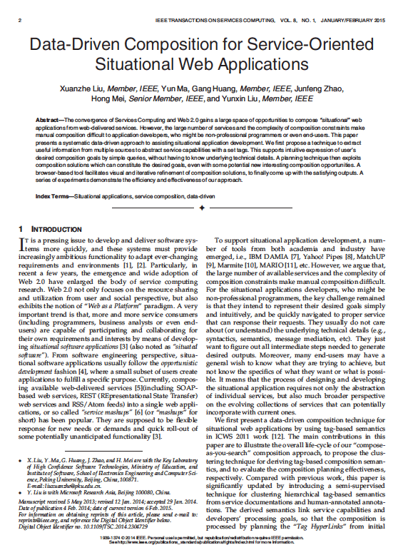
| ASP.NET XML WEB SERVICES | Windows Forms |
| Base Class Libraries | |
| Common Language Runtime | |
| Operating System |
Fig1 .Net Framework
C#.NET is also compliant with CLS (Common Language Specification) and supports structured exception handling. CLS is set of rules and constructs that are supported by the CLR (Common Language Runtime). CLR is the runtime environment provided by the .NET Framework; it manages the execution of the code and also makes the development process easier by providing services.
C#.NET is
a CLS-compliant language. Any objects, classes, or components that created in
C#.NET can be used in any other CLS-compliant language. In addition, we can use
objects, classes, and components created in other CLS-compliant languages in
C#.NET .The use of CLS ensures complete interoperability among applications,
regardless of the languages used to create the application.
CONSTRUCTORS AND DESTRUCTORS:
Constructors are used to initialize objects, whereas destructors are used to destroy them. In other words, destructors are used to release the resources allocated to the object. In C#.NET the sub finalize procedure is available. The sub finalize procedure is used to complete the tasks that must be performed when an object is destroyed. The sub finalize procedure is called automatically when an object is destroyed. In addition, the sub finalize procedure can be called only from the class it belongs to or from derived classes.
GARBAGE COLLECTION
Garbage Collection is another new feature in C#.NET. The .NET Framework monitors allocated resources, such as objects and variables. In addition, the .NET Framework automatically releases memory for reuse by destroying objects that are no longer in use.
In C#.NET, the garbage collector checks for the objects that are not currently in use by applications. When the garbage collector comes across an object that is marked for garbage collection, it releases the memory occupied by the object.
OVERLOADING
Overloading is another feature in C#. Overloading enables us
to define multiple procedures with the same name, where each procedure has a
different set of arguments. Besides using overloading for procedures, we can
use it for constructors and properties in a class.
MULTITHREADING:
C#.NET also supports multithreading. An application that supports multithreading can handle multiple tasks simultaneously, we can use multithreading to decrease the time taken by an application to respond to user interaction.
STRUCTURED EXCEPTION HANDLING
C#.NET supports structured handling, which enables us to
detect and remove errors at runtime. In C#.NET, we need to use
Try…Catch…Finally statements to create exception handlers. Using
Try…Catch…Finally statements, we can create robust and effective exception
handlers to improve the performance of our application.
7.5 THE .NET FRAMEWORK
The .NET Framework is a new computing platform that simplifies application development in the highly distributed environment of the Internet.
OBJECTIVES OF .NET FRAMEWORK
1. To provide a consistent object-oriented programming environment whether object codes is stored and executed locally on Internet-distributed, or executed remotely.
2. To provide a code-execution environment to minimizes software deployment and guarantees safe execution of code.
3. Eliminates the performance problems.
There are
different types of application, such as Windows-based applications and Web-based
applications.
7.6 FEATURES OF SQL-SERVER
The OLAP Services feature available in SQL Server version 7.0 is now called SQL Server 2000 Analysis Services. The term OLAP Services has been replaced with the term Analysis Services. Analysis Services also includes a new data mining component. The Repository component available in SQL Server version 7.0 is now called Microsoft SQL Server 2000 Meta Data Services. References to the component now use the term Meta Data Services. The term repository is used only in reference to the repository engine within Meta Data Services
SQL-SERVER database consist of six type of objects,
They are,
1. TABLE
2. QUERY
3. FORM
4. REPORT
5.
MACRO
7.7 TABLE:
A database is a collection of data about a specific topic.
VIEWS OF TABLE:
We can work with a table in two types,
1. Design View
2. Datasheet View
Design View
To build or modify the structure of a table we work in the table design view. We can specify what kind of data will be hold.
Datasheet View
To add, edit or analyses the data itself we work in tables datasheet view mode.
QUERY:
A query is
a question that has to be asked the data. Access gathers data that answers the
question from one or more table. The data that make up the answer is either
dynaset (if you edit it) or a snapshot (it cannot be edited).Each time we run
query, we get latest information in the dynaset. Access either displays the
dynaset or snapshot for us to view or perform an action on it, such as deleting
or updating.
CHAPTER 7
7.0 APPENDIX
7.1 SAMPLE SCREEN SHOTS:
7.2
SAMPLE SOURCE CODE:
CHAPTER 8
8.1 CONCLUSION AND FUTURE:
In this paper, we proposed architecture for real-time Big Data analysis for remote sensing applications in the architecture efficiently processed and analyzed real-time and offline remote sensing Big Data for decision-making. The proposed architecture is composed of three major units, such as 1) RSDU; 2) DPU; and 3) DADU. These units implement algorithms for each level of the architecture depending on the required analysis. The architecture of real-time Big is generic (application independent) that is used for any type of remote sensing Big Data analysis. Furthermore, the capabilities of filtering, dividing, and parallel processing of only useful information are performed by discarding all other extra data. These processes make a better choice for real-time remote sensing Big Data analysis.
The algorithms proposed in this paper
for each unit and subunits are used to analyze remote sensing data sets, which
helps in better understanding of land and sea area. The proposed architecture
welcomes researchers and organizations for any type of remote sensory Big Data
analysis by developing algorithms for each level of the architecture depending
on their analysis requirement. For future work, we are planning to extend the
proposed architecture to make it compatible for Big Data analysis for all
applications, e.g., sensors and social networking. We are also planning to use
the proposed architecture to perform complex analysis on earth observatory data
for decision making at realtime, such as earthquake prediction, Tsunami
prediction, fire detection, etc.